![]()
Revised
31/12/2011
.
|
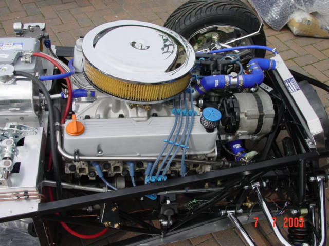
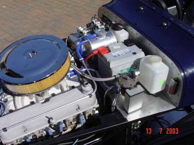
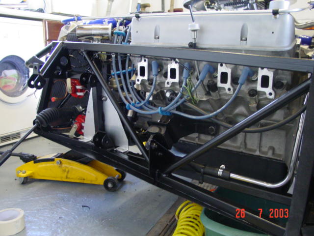
I had set myself the task of trying to have the engine running for Saturday 5th July, not sure why but it gave me a date to work towards. Having looked at the list of things to do before starting the engine, I ended up with a long shopping list which revolved around coolant hoses and electrics. I also wanted to check on oil pressure and engine temperature so needed to buy a set of gauges. First job was to find out how to wire up the engine loom. I came across the schematic shown below for the wiring arrangement for the coil, distributor and ballast resistor, all standard lucas items which were new so shouldn't need replacing or upgrading for a while yet. Note that with the starter motor, the brown / yellow wire from the ballast resistor goes to the smaller bottom screw terminal marked IGN, whilst the red/white wire from the ignition goes to the larger top screw terminal. The oil pressure light was wired in following the Haynes manual. The oil pressure sender for the oil pressure gauge was fixed into the top of the remote filter housing by drilling and tapping a hole.
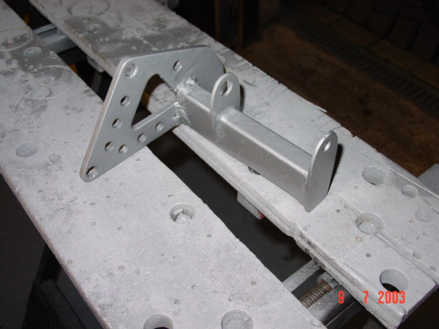
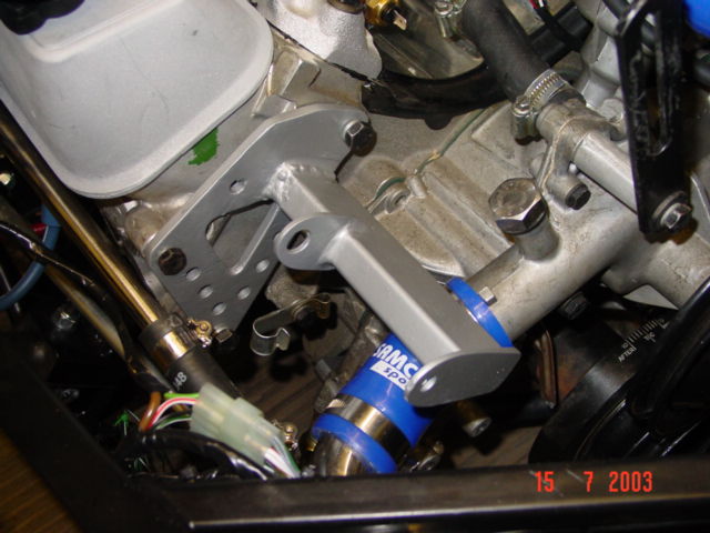
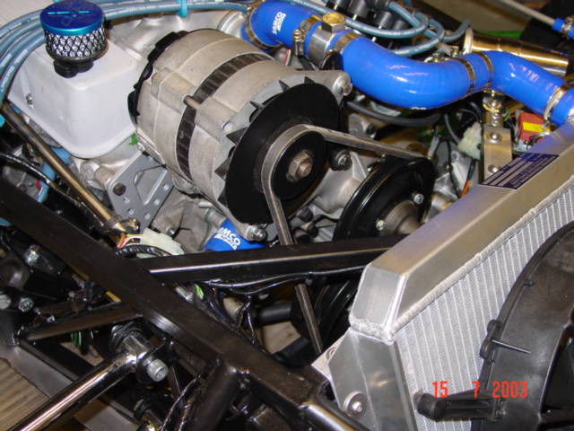
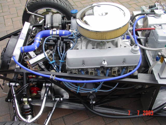
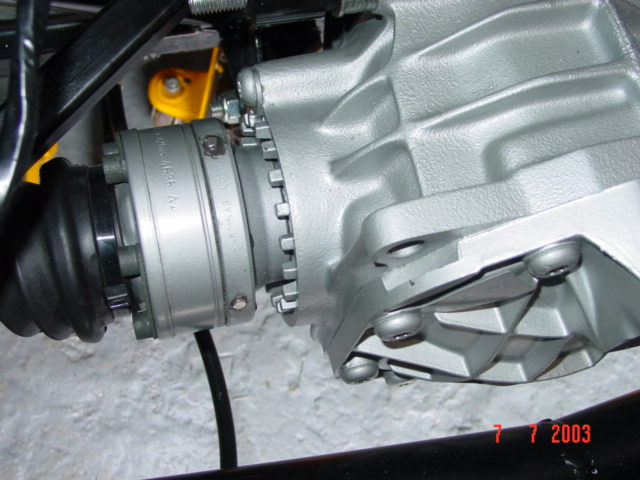
Having read about all the problems with the alternator position, I was lucky that the alternator bracket which had come with the engine was a fabricated one, rather than a standard SD1 or P6 unit. The arm on the bracket was cut off and re-welded to position the alternator lower down. The casing on the alternator was unbolted and spun round to allow the adjuster to be positioned to the right hand side of the alternator. Before the alternator was fitted, the heater return inlet on top of the water pump was plugged by tapping the inlet and inserting a M16 stainless steel bolt. An alternative, as recommended to me by Chris Bell would be to attach a short length of hose with the bolt inserted and held in place with a jubilee clip.
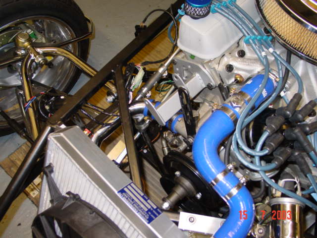
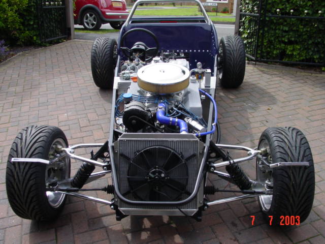
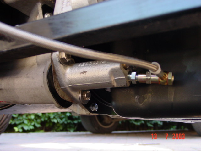
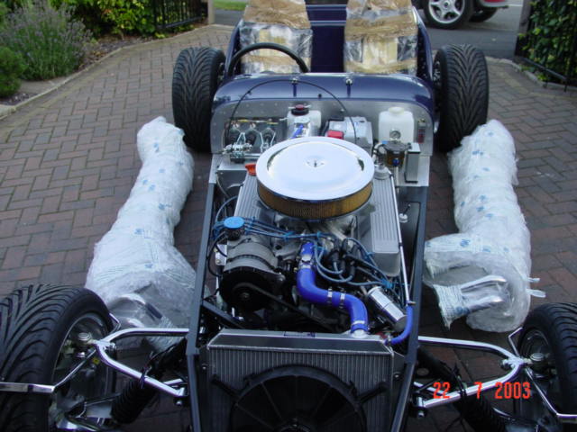
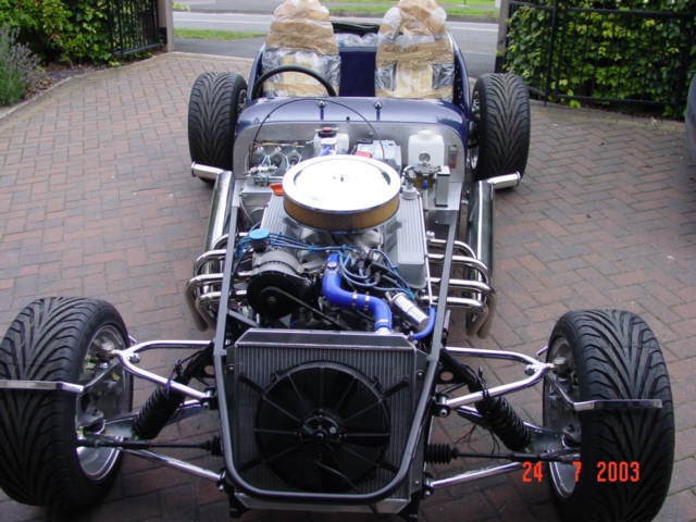
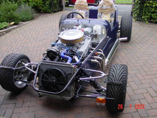
I was reluctant to move the distributor before I had heard the engine running, but it seemed as though it would be very difficult to install the top radiator hoses with them clashing with the vacuum take-off without having the thermostat housing altered. Having read a web page detailing fitting a V8 in an MGB where there was a similar problem, the solution seemed to be to spin the distributor (described as when looking from front with vacuum take off at 10 o 'clock spin distributor anti-clockwise until vacuum take off is at 6 o'clock). This did mean that all the plug leads would need to be repositioned to suit. I decided to buy a set of Moroso leads from Real Steel which you cut to length, which would give me more flexibility when choosing a suitable route around the engine bay. Although I had packed the oil pump with Vaseline, with the distributor off, I decided to spin the oil pump with a drill. A piece of threaded bar was used with a slot cut in the end with an angle grinder. It was encouraging to see the oil light go out and pressure gauge begin to rise when the bar was spun. The first big problem before starting the engine was setting the timing. There was a timing pointer on the engine when I had bought it, but it had been removed when the power steering pully was being removed. I had seen the pointer over the past few months kicking around the garage but couldn't find it now. A few phone calls later and still no look. Even Rimmer Bros who have them listed at 90p each said they couldn't get them any more. TDC was roughly found by poking a cable tie down No 1 cylinder and guessing when it had reached the top and a piece of aluminium was fabricated as a temporary pointer. The big moment had arrived, the car was pushed out on the drive and ignition key turned . The fuel pump started clicking and fuel regulator began filling up with petrol. At the first full turn of the key the engine fired up instantly - what a noise !
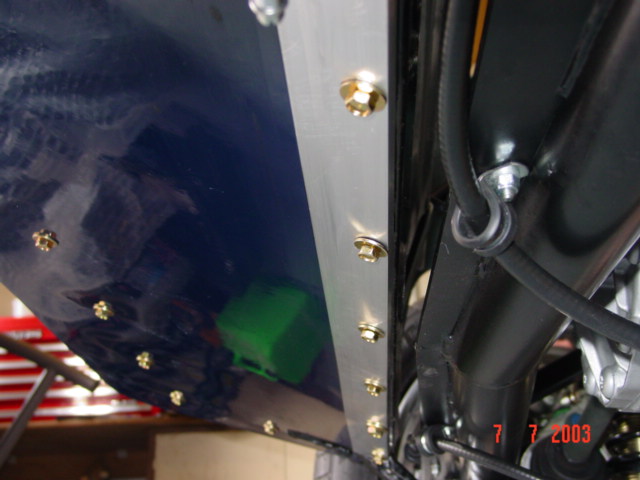
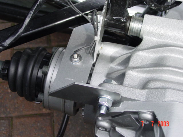
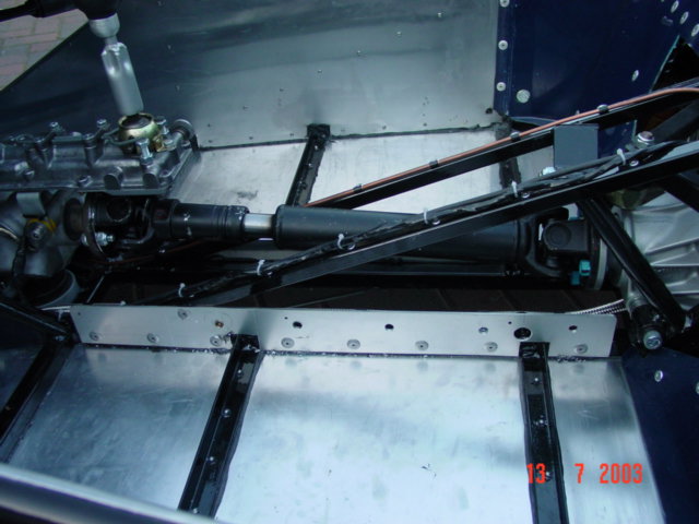
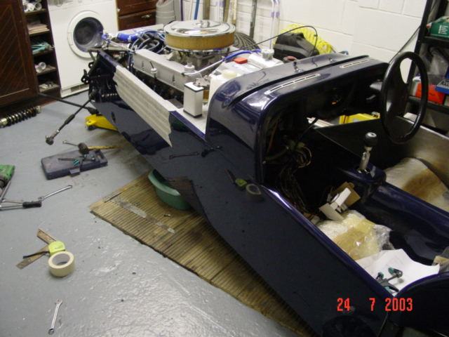
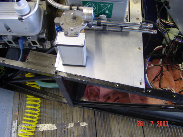
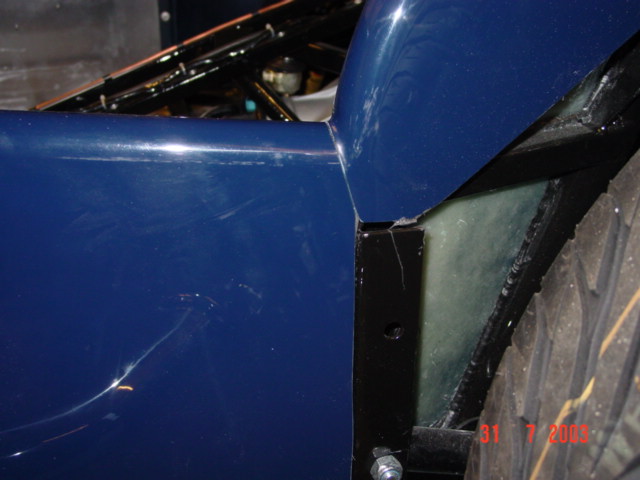
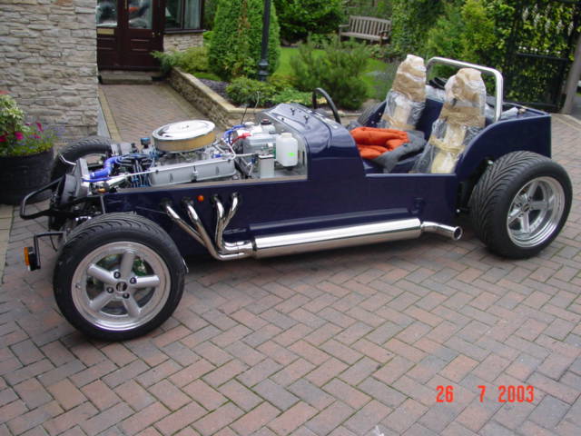
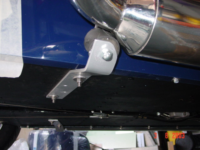
Confident that the engine worked, I was eager to get the exhausts fitted. With the engine working, the end was in sight. Typical then of Dax to throw a spanner in the works. I had been told that my exhaust was being made the previous week. However on ringing Dax, I was told that it would be 3 to 4 weeks before it would be ready ! How, when I was told they had already started making it. This was met with the usual excuses of them being busy and illness and holidays, etc, etc. After letting off a bit of steam ! I was told that they would re-work their schedule and have it finished the following week - I will have to wait and see. For anyone reading this who is contemplating buying a kit, order your exhaust when you first place your order for the kit or better still go somewhere else ! A 40 x 10mm aluminium angle was fixed to the underside of the rear tub to bridge the gap between the GRP and the chassis rail. As the next milestone was going to be fixing the transmission tunnel in place, the remaining cable had to be fitted. This was the magnetic sensor for the speedometer. An aluminium bracket was fabricated to hold the sensor and 4 magnets glued into position of the driveshaft. To ensure there was a good bond onto the driveshaft, I formed an indent in the 4 positions by drilling a shallow hole with an oversized drill bit.
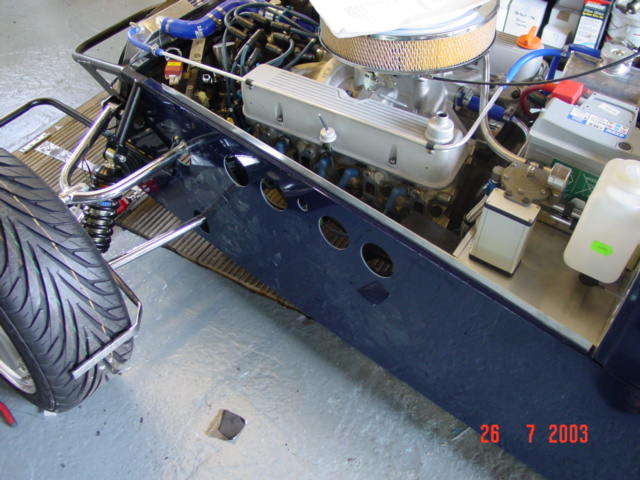
Most of the time in the past week seems to have been spent tidying up the routing of the plumbing and electrics in the engine bay. I have decided against fixing the heater bypass valve at this stage but may fit it later after SVA. I finally managed to source a timing pointer, along with a lower cover plate for the bellhousing, and bush spacers for fixing the remote gearshift housing from D J Ellis.
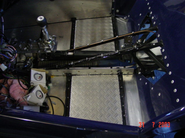
When coming to fix the transmission tunnel, as others have found, the bottom flange of the GRP does not fit tightly against the floor panels. The plan was to fix the GRP to the chassis members using rivnuts but this meant that there wasn't much material at the bottom of the tunnel moulding to pull against. The bottom flange of the moulding was carefully cut off using a hacksaw blade and a 3mm aluminium strip, 70mm wide pop riveted to the lower chassis member to allow the rivnuts to be positioned approximately 50mm up from the bottom of the moulding.
|


![]()
|
Registration speedo sensor, bonnet catches, final trim, MOT & SVA Nosecone, Rear tub, front mudguards, alarm Finishing fitting the dashboard Carpets, seats and Dashboard Making a start on the interior Lights working Bonnet, Nosecone, Headlights 1st drive Rear mudguards and lights Engine loom wiring, Alternator bracket, Distributor, Engine Started, Speedo sensor, Transmission tunnel fitting, Exhausts, Side panels Steering column, Front axle, Pedal box, Wheel studs, Fuel tank, Wiring loom, Rear tub, Remote oil filter, Front bulkhead / battery shelf, Column switches Footwell panels, Rear axle, Brake pipes, Rear bulkhead, Fuel pump, Engine installed Collect kit from Dax, Painting chassis, Remote oil filter takeoff plate, Floor panels, A frame bushes Gearstick remote, Baffled sump Preparing LT77 gearbox, exhaust options, Costs for kit 3.62:1 LSD Front hub bearings, Engine age Preparing donor differential, drive shafts, hubs |
|
|